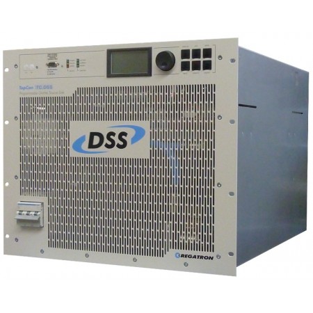
Regatron TC LIN 26 / 40 / 45 / 75 kW
Description
Alimentations Regatron TC LIN - 26 / 40 / 45 / 75 kW
Overview
Solar Array Simulation is one important part of testing solar inverters. One of the most important characteristics is the ability to find and track the operating point where the maximum of energy offered by the solar cell: this is called to find/track the maximum power point (MPP). Due to the long usage of the solar system, even a slight discrepancy results in a significant loss of energy gathered over time and hence in monetary loss.
Solar inverters implement different strategies how to find that maximum. Some special algorithms demand for a very high accuracy of the simulation of the solar cell. In such cases the linear post-processing unit TC.LIN.SER (TC.LIN) is the matching extension to be combined with the TopCon power supply. In particular when exploiting the unique application area processing (AAP) functionality e.g. to simulate the characteristic functional solar cell curve I = f(V), the performance and accuracy of the power supply system increases significantly.
Model range / palette / data sheets
The following table lists the models in the TC.LIN family. Other models with different characteristics compared to the standard models are available on request. The related modified data will then apply.
| Max output power | Max input voltage | Max output current | Data sheet / type ID |
| 26 kW | 1000 VDC | 13 A / 26 A 1) | TC.LIN.26.1000.26 |
| 40 kW | 1000 VDC | 20 A / 40 A 1) | TC.LIN.40.1000.40 |
| 45 kW | 1000 VDC | 22 A / 45 A 1) | TC.LIN.45.1000.45 |
| 75 kW | 1500 VDC | 25 A / 50 A 1) | TC.LIN.75.1500.50 |
1) The first value relates to the "alternative range of current" setting, the second to the “full range”.
The alternative current range is a second range of settings. Switching from the full to the alternative current mode, changes the accuracy of the measurement as the absolute accuracy depends on the full scale value. In the existing model palette, all models are shipped with the alternative current range being half of the full range. This results in double absolute accuracy of current measurement.
Tasks with higher power (current) characteristics can be realised by connecting various TC.LIN in parallel. As the control of the TC.LIN is transparent to the user, the whole TopCon + TC.LIN system is controlled as usually: from TopControl software or another control interface.
With the "License to improve" of the TopCon signal
The TC.LIN is linked into the DC connection between the TopCon power supply and the device under test (DUT). All data is sent from the TopCon ps to the TC.LIN by exploiting the fast transmission of the system CAN bus. Thus the AAP characteristics is delivered from the TopCon device to the TC.LIN just prior to using it in the TC.LIN. Then the signal of the TopCon is amended by the operations of the TC.LIN. Operating and configuration of the TC.LIN is achieved by doing it on the TopCon device and then transparently delivered to the TC.LIN.
TopCon / TC.LIN Systems

Scenario: Usage in solar array simulation
In many applications the dynamic control performance of the TopCon DC power supply is completely adequate for the required application. An example is Solar Array Simulation (SAS). The function engine, TFE, built into the power supply permits, with the AAP functionality, the simulation of the behaviour of a solar panel ( I=f(V) characteristic). The general function, quality, efficiency as well as other characteristics of the inverter can be tested and measured. Some inverter models require a dynamic performance closer to reality for the optimum function of their MPP tracker; this performance is achieved by connecting in series a linear-controlled series controller. The TC.LIN.SER linear post-processing unit contains, along with a highly dynamic linear power stage, a very fast digital control structure that, combined with the power supply, provides the required improvement in dynamic performance.


| Puissance | 10, 16, 20, 32 kW |
| Tension | 0...1200V par module |
| Courant | 0...700A par module |
| Informations | Rendement jusqu'à 95% |